Analyze and define the manual task map Most collaborative robot applications start off as a manual operation. They feature a locking solenoid and an internal release to prevent an operator from becoming trapped inside the robot cell.

Abb S 3dqi Robot Cell Accelerates Quality Control Testing Robot Welding Projects Robotic Automation
02-Chapter 2-Part 1 Robot Work Cell Design and Controlpdf.

. IN-LINE ROBOT WORK CELL There are 3 types of work part transport systems used in in-line robot work cell. Robot cell design Robot work cell can be organised in to various arrangements or layouts. Below a detailed description of the project key robotics technologies employe d in the development of the workcell and the design process will be presented.
CHAPTER ELEVEN ROBOT CELL DESIGN AND CONTROL Industrial robots generaliy work with other pieces of equipment. Plant survey to identical potential applications. SKEM4153 ROBOT TECHNOLOGY FOR.
You can also decide if the height of the positioner will be fixed or adjustable. Here RC stands for the robot cell. Work Cell Design and Control Chapter 5 fContents Robot Cell Layouts Multiple Robots and Machine Interface Some Consideration in Work Cell Design Interlocks Error Detection and Recovery Robot Cycle Time Analysis fIntroduction Step of a company to implement a robotics program in its operation.
For light work Minimize lifting Follow a rhythm Cellular Flow. Determine if robotic vision is needed for your application. This is all about the spacing within the work cell.
You should begin by analyzing how human workers are currently performing the task. 54There are 3 types of work part transport system used in in-line robot work cell. What is a robot cell.
Work Cell Design and Control PowerPoint presentation free to view - id. Textbook Solutions Expert Tutors Earn. View Notes - Lecture Robot Cell Design and Control from ISE 324 at University of Ottawa.
02-Chapter 2-Part 1 Robot Work Cell Design and Controlpdf. Intermittent Transfer 2Continuous Transfer3Non-Synchronous Transfer Intermittent TransferThe parts are moved in a start-and-stop motion from one station to another along the line. Vector indicates the cell with n identical workstations at each stage and m robots.
The robotic cell design is indeed a job to translate manual or semi-automated operation to a robotized solution. A robot based manufacturing cell system we can consider as a closed system within some large unit workshop. Total idle time of all three machines is 3 x 10 30 s The cycle time of the robot is 3 x 20 60 s Therefore machine interference is 30 s 60 s 50 19.
IN-LINE ROBOT WORK CELL There are 3 types of work part transport systems used in in-line robot work cell. Intermittent Transfer System The parts are moved in a start-and-stopmotion from one station to another along theline. About Press Copyright Contact us Creators Advertise Developers Terms Privacy Policy Safety How YouTube works Test new features Press Copyright Contact us Creators.
You should begin by analyzing how human workers are currently performing the task. Non-synchronous Transfer 10 IN-LINE ROBOT WORK CELL 1. Background The objective for the project to be discussed is to design and develop a portable robotic w orkcell.
Method of work part delivery eg. 02-Chapter 2-Part 1 Robot Work Cell Design and Controlpdf. This type of layout is used for the operations like arc welding die casting.
CHAPTER ELEVEN ROBOT CELL DESIGN AND CONTROL Industrial robots generaliy work with other pieces of equipment. Systems integration software design as well as an electrical sy stems design. The positioner should either be fixed or mobile and the weight capacity of the positioner should be examined as well.
The Adobe Flash. Conveyors parts feeders and pallets are used for delivering the workpart in andor out of the cell. 02-Chapter 2-Part 1 Robot Work Cell Design and Controlpdf.
Map out the exact location of all of the inputs outputs human work areas and the robot itself. A robotic work cell is a complete system composed of one or more robots and a controller. There was a problem previewing 02-Chapter 2-Part 1 Robot Work Cell Design and Controlpdf.
Intermittent Transfer System The parts are moved in a start-and-stop motion from one station to another along the line. Formal description of a robotized manufacturing system is the following. Select a positioner to move the product down the line.
There will be resulting machine interference. The four cell layout design steps are. A robotic work cell is a complete system composed of one or more robots and a controller.
Intermittent Synchronous Transfer 2. The positioner will contain your product while the robots are manufacturing. View 02-Chapter_2_Robot_Work_Cell_Design_and_Control_Finalpdf from MECHANICAL 405 at Guru Gobind Singh Indraprastha University.
When parts enter the work cell exact pick up and drop off locations as well as part orientations must be specified in. 02-Chapter 2-Part 1 Robot Work Cell Design and Controlpdf. Work cell controlSequence controlOperator interfaceSafety monitoring26 Sequence controlSequence control includesRegulate the sequence of activitiesControl of simultaneous activitiesMaking decision toproceedstopdelay work based onevents27 28 29 Operator InterfaceOperator to interact with robot work cell.
Conveyor part-feeders pallets. Vi control of the work cell the activities of the robot must be coordinated with those of the other equipment in the work cell. This chapter outlines many of the design and selection decisions of.
Initial familiarization with the technology. Non-synchronous Transfer 15 IN-LINE ROBOT WORK CELL 1. Note that the feed-in and feed-out devices can be regarded as the special workstations so that they are denoted as Ws 1 and Ws n respectivelyThe superscript Gr denotes the gripper type say single- or dual-gripper while the subscript Lo.
The system can be described with the help of dimensioning its main parts giving the relationships between them and forming the structure of the system. When the robot cycle time is greater than the machine cycle time. To increase the utilization the workcell concept was developed in which one robot services several machines as shown in the figure.
Machine Interference In the example above. The idea here is to use your manual task as a starting point for the robotic cell.

Pin On Technology

Staubli Rx90 6 Axis Robot Arm Cs7 Controller With Or Without Work Cell Rx 90 Robot Arm Industrial Robotic Arm Robot

Pin On Industry 4 0

Kuka Robot Machining Jx 200rg Industrial Robots Robot Design Robotic Automation
1

Work On State Of The Art Robotics Equipment Http Watc Edu Manufacturing Degree Certificate Programs Robotic Robotic Automation Abb Robotics Business Reviews
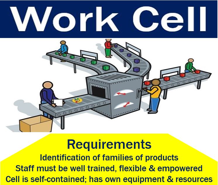
Work Cell Definition And Meaning Market Business News
Robot Cell Design Robotic Automation Robot Robotic Welding
0 comments
Post a Comment